There is a choice of two Vector Extraction methods for WinTopo Pro. Vector Extraction is the process of actually fitting vectors to the raster pixel lines.
You can choose the options by clicking the ![]() toolbar button, to get this window:
toolbar button, to get this window:
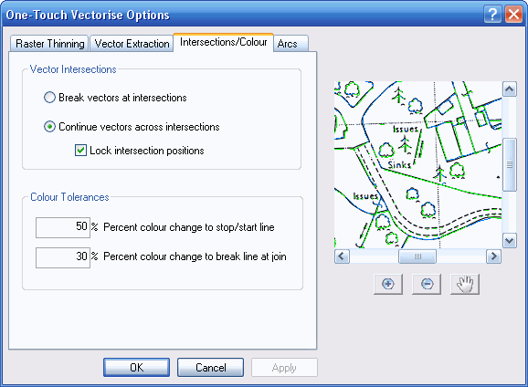
The first option, Break vectors at intersection, is the method used by WinTopo Freeware, but can also be selected in WinTopo Pro. With this option, WinTopo will stop a polyline at the intersection with any other line. This ensures that a node is placed at every intersection on the vector drawing.
The second option is Continue vectors across intersections. This is the default option for WinTopo Pro, and is not available in WinTopo Freeware. With this option WinTopo Pro does not have to stop the polylines at intersection, but instead tries to intelligently continue the lines through the intersections, using information in the image to determine the direction that each line takes at the intersection. You can use the Colour Tolerances to configure the process. See the explanation below.
Lock Intersection Positions This option is is not available in the Freeware version With this option selected WinTopo Pro will not allow movement of the line intersection points by the PolyLine Smoothing, Polyline Reduction or Arc Recognition stages of vectorisation. This will generally result in better corners on engineering type drawings. It also ensures that T-junction intersections stay joined up, otherwise the PolyLine Smoothing, Polyline Reduction or Arc Recognition functions can drag the junction apart.
These two settings affect how WinTopo extracts colour vectors from colour rasters. The values have no effect on a monochrome raster image.
These settings can improve results for rasters with lines containing pixels which vary in colour significantly, but where the overall colour of a line is fairly constant.
Here is a magnified example of a section of a colour raster, comprising a brown line of pixels crossing a red line of pixels. You can see that there is a wide variation in pixel colour along each pixel line. On the right is the default vectorisation.
You will see that the default vectorisation handles the red line in a way that may be undisirable:
The first of these 'problems' can be rectified by changing the Percent colour change to start/stop line tolerance value. This value represents the amount pixels along a line must change in colour before WinTopo stops the polyline and starts a new one. Remember that a polyline is all one colour.
If this value is increased from the default 30% up to 50% then we get the following result:
Here you can see that the two halves of the red polyline are each a single colour, but the line is still broken at the intesection with the brown line.
To rectify the second 'problem' you can increase the Percent colour change to break line at join tolerance value. This value represents the percentage colour difference polylines must have to prevent WinTopo joining them through an intersection.
By increasing this value from the default 10% up to 30% we get the following result:
This result also benefits by producing less vectors - only 2 polylines, comprising 8 vectors. The first default vectorisation produced 8 polylines comprising 14 vectors.
Why not keep the Colour Tolerances high all the time?
For images with lines containing pixels of more uniform colour, the lower tolerances perform better. Consider the following raster extract, with similar pixel lines to the above example, but with pixels of less variable colour.
In this example, the red and brown lines of pixels change direction at the intersection, instead of crossing each other.
If we vectorise with the Percent colour change to break line at join at the higher value of 30% from the example above, then we get the following result:
You can see that two polylines are produced which cross at the intersection, and are both an averaged red-brown colour. This is because the colour of the two pixel lines is different by less than 30%.
What would be preferable is to have a red polyline following the red pixels and a brown polyline following the brown pixels.
If we run the vectorisation with the default Percent colour change to break line at join setting of 10%, then WinTopo Pro follows the pixel colour in preference to making the lines continue straight through at the intersection. This is because the colour of the two pixels lines is different by more than 10%:
Related Topics: